
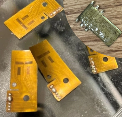
These are full wheatstone bridge strain gauges - note the production quality of the old version (top right) vs mine
I dialed in power / speed / pulse rate to hit 1000 Ω ±10 Ω (down from ±90 Ω). Other manufacturing improvements include:
rolling infill epoxy on with pipette vs smearing
pre-soldering contact pads
respaced traces to reduce HAZ- induced failures
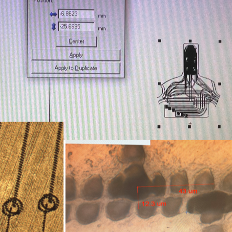
The UV laser only cuts effectively inside an area ~25 mm in diameter. We needed to cut much larger samples, so I found a solution; rotate the work under the beam and stitch multiple cuts together like pieces of a pie. (New effective diameter = 52mm)
I SLA-printed 30° indexed male/female “star” wedges (show on the left image) for repeatable positioning + wrote an SOP on how to calibrate the stage & software. (the right image shows steps of calibration)
Result: Within 5 µm true position across 12 index steps — stable enough to stitch larger patterns reliably. (stitch alignment is shown in bottom left of right image)
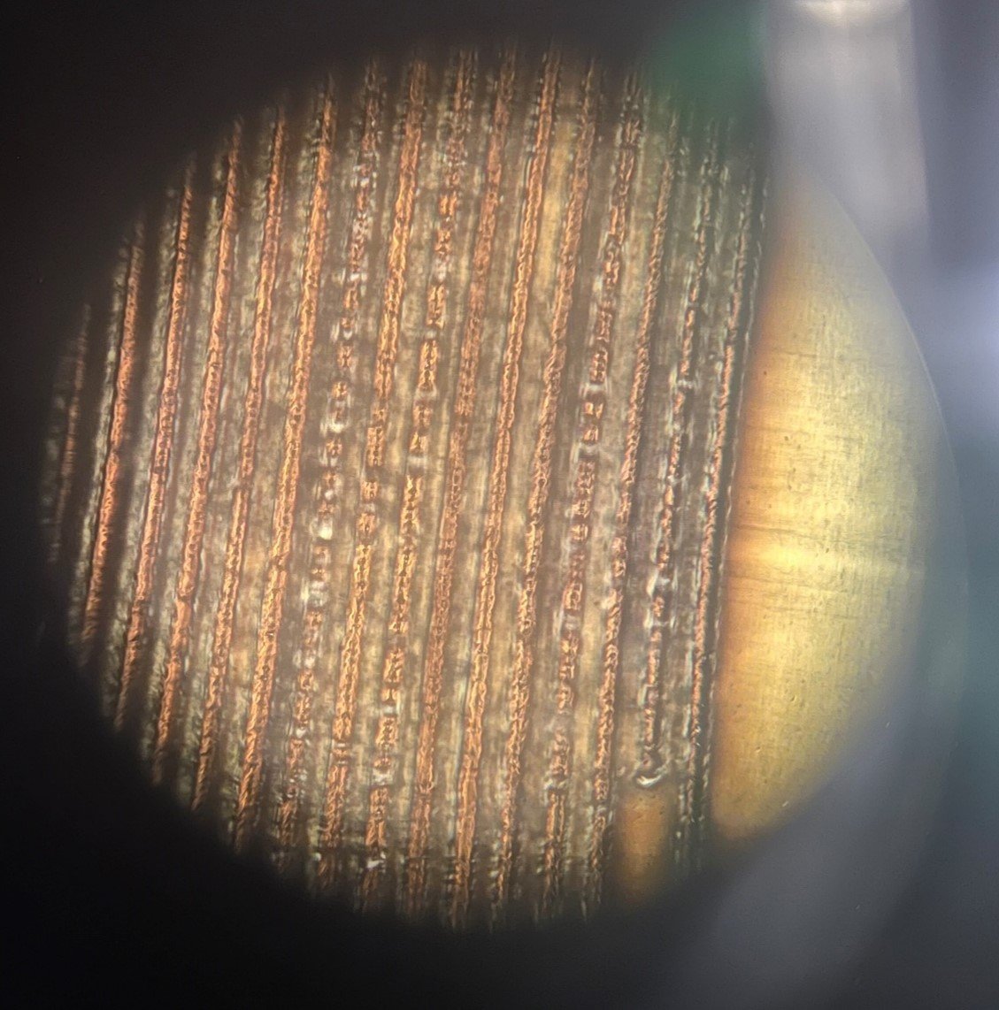
This is a 20x zoom on the strain guage resistor traces - revealing the laser can melt/reweld material, leaving those tiny “bridges” you see between the lines
This shorts the circuit and drops resistance below spec.
I found that low resistance isn’t just “too little power = not cutting the NiCr”, faults are often caused by minimal pulse overlap
Used this insight to avoid the short circuits and get clean, repeatable cuts.
Sept-Dec 2025: Thin Film Sensor Manufacturing Research @ Uwaterloo CAMJ
At CAMJ under Prof. Peng, I prototyped thin-film strain sensors for ForceN by UV laser-cutting NiCr traces, then validated resistance and cut quality under a microscope. This section shows the process improvements, failure analysis, and the indexing platform I built to expand the cutting envelope for larger designs.
Sept-Dec 2025: Thin Film Sensor Manufacturing Research @ Uwaterloo CAMJ

-
These are full wheatstone bridge strain gauges - note the production quality of the old version (top right) vs mine
I dialed in power / speed / pulse rate to hit 1000 Ω ±10 Ω (down from ±90 Ω). Other manufacturing improvements include:
rolling infill epoxy on with pipette vs smearing
pre-soldering contact pads
respaced traces to reduce HAZ- induced failures
-
This is a 20x zoom on the strain gauge resistor traces - revealing the laser can melt/reweld material, leaving those tiny “bridges” you see between the lines
This shorts the circuit and drops resistance below spec.
I found that low resistance isn’t just “too little power = not cutting the NiCr”, faults are often caused by minimal pulse overlap
I used this insight to avoid the short circuits and get clean, repeatable cuts.
-
The UV laser only cuts effectively inside an area ~25 mm in diameter. We needed to cut much larger samples, so I found a solution; rotate the work under the beam and stitch multiple cuts together like pieces of a pie. (New effective diameter = 52mm)
I SLA-printed 30° indexed male/female “star” wedges (show on the left image) for repeatable positioning + wrote an SOP on how to calibrate the stage & software. (the right image shows steps of calibration)
Result: only ~5 µm of runout across 12 index steps (measured at ~20 mm radius) — stable enough to stitch larger patterns reliably. (stitch alignment is shown in bottom left of right image)
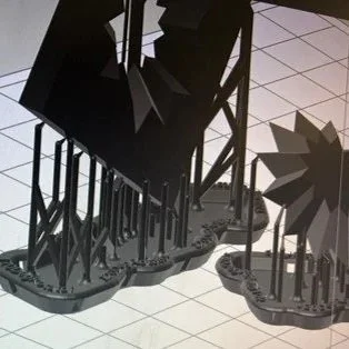
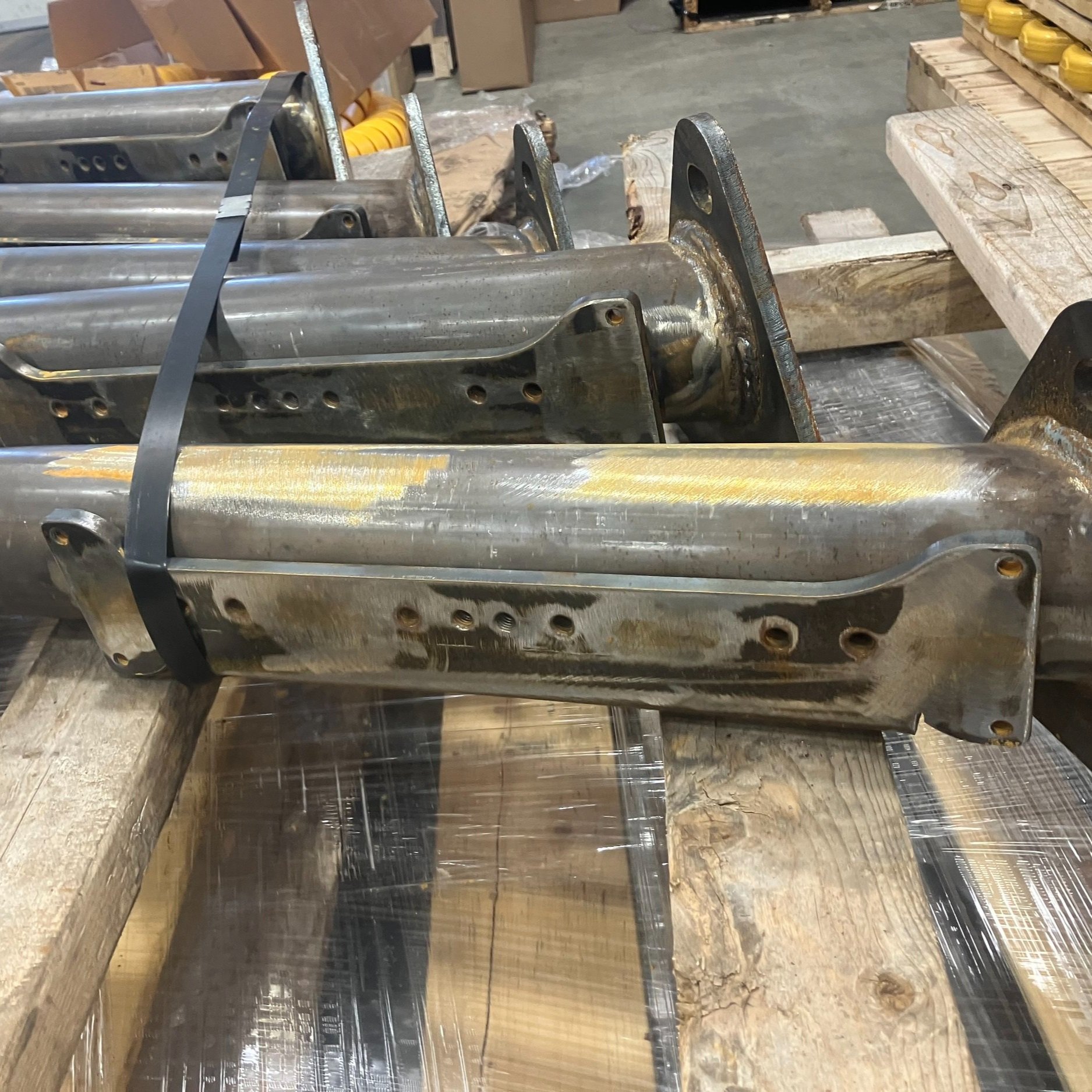
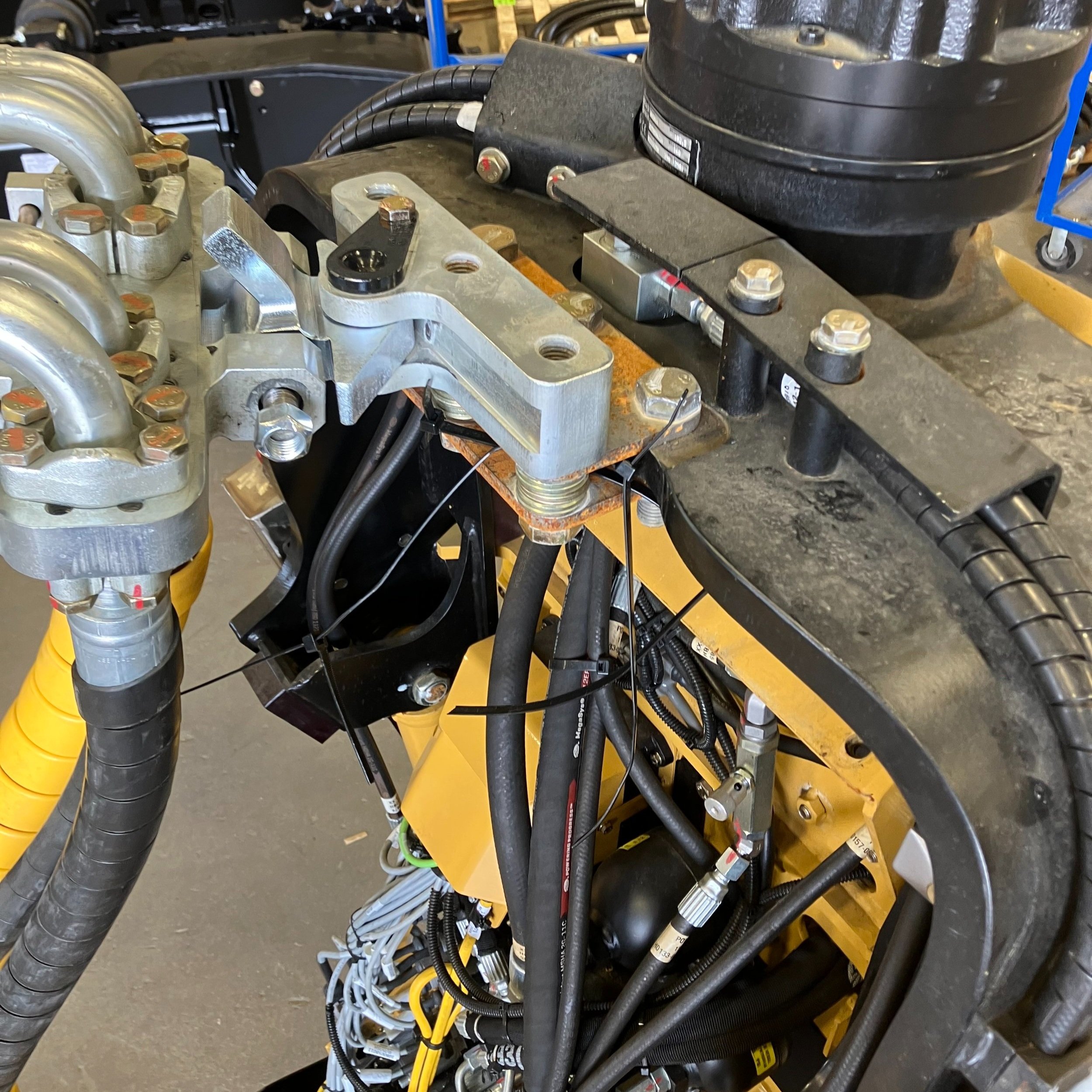
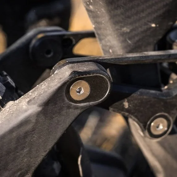
Problem: Hydraulic cables are strained by rotation of cutting head.
My solution:
machining and iterating this swivel gallery + swivel head to control hose/cable routing near the head (this greatly reduced snag/chafe risk and improving reliability).
I prototyped quickly, tested fit/function, then refined toward a manufacturable solution.
This is the 1165 harvester
One project was designing a wiring harness for new leveling sensors: that meant finding new routing paths, new mounting hardware, connector selection, testing, and through to updating manufacturing drawings.
Another project was reverse-engineering a competitor’s joystick control pods so an operator switching brands could keep familiar control feel.
May-Aug 2024: 1165 Harvester Product Design @ TIGERCAT
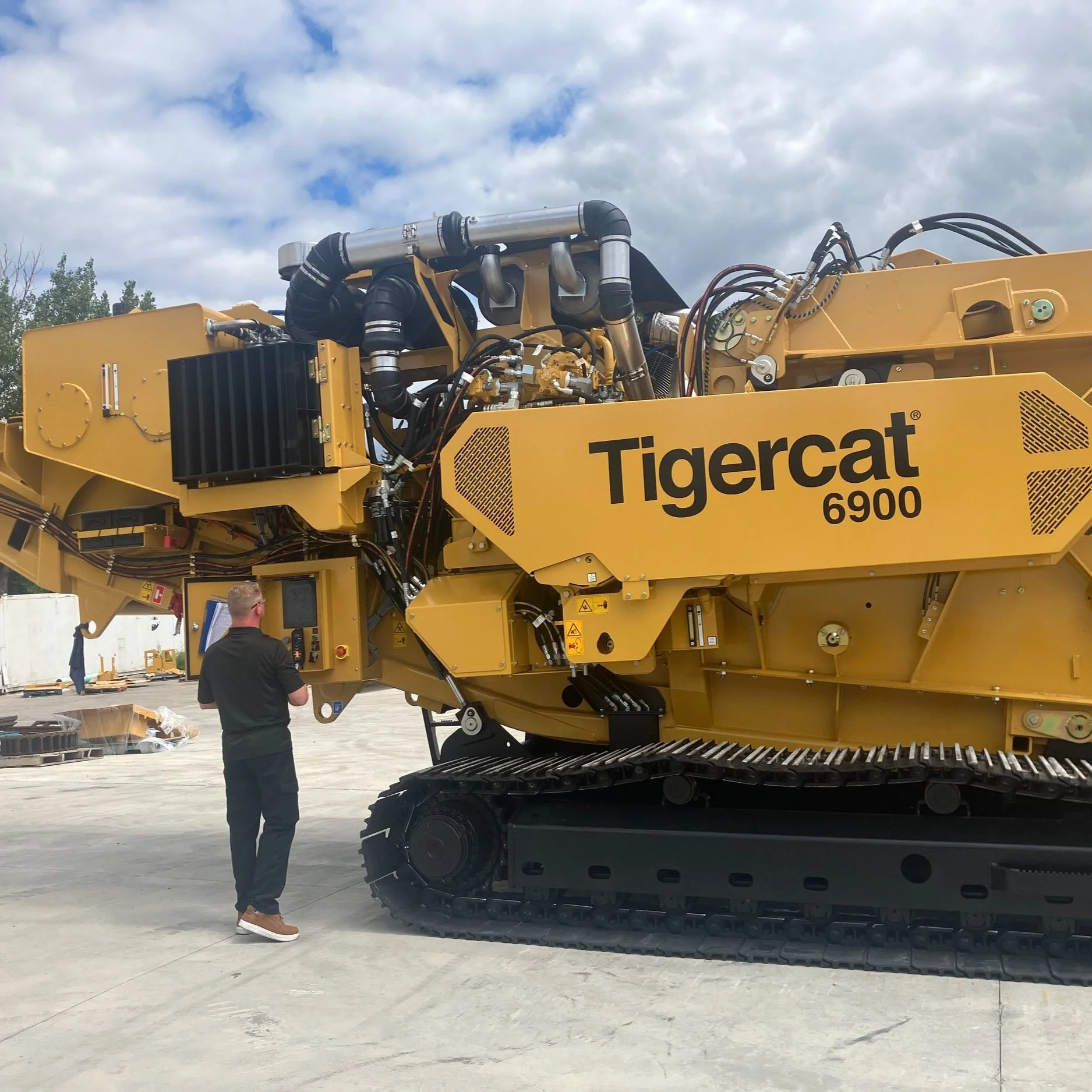
At Tigercat, I supported product design work on the 1165 wheel harvester—a machine built for steep-terrain forestry with features like a leveling cab/crane and a dedicated hydraulic system for drive/head/crane functions.
I learned how to ship changes inside a large, multi-site manufacturing organization
These are Fire extinguisher mounting brackets
I designed the whole production; packaging, laser-cutting, site to site delivery, forming, tapping & welding.
This simple bracket taught me large-company execution: revision control, clear drawings/BOM discipline, and cross-site communication to get these built correctly the first time.

-
Problem: Hydraulic cables are strained by rotation of cutting head.
My solution:
machining and iterating this swivel gallery + swivel head to control hose/cable routing near the head (this greatly reduced snag/chafe risk and improving reliability).I prototyped quickly, tested fit/function, then refined toward a manufacturable solution.
-
This is the 1165 harvester
One project was designing a wiring harness for new leveling sensors: that meant finding new routing paths, new mounting hardware, connector selection, testing, and through to updating manufacturing drawings.
Another project was reverse-engineering a competitor’s joystick control pods so an operator switching brands could keep familiar control feel.
-
These are Fire extinguisher mounting brackets
I designed the whole production; packaging, laser-cutting, site to site delivery, forming, tapping & welding.
This simple bracket taught me large-company execution: revision control, clear drawings/BOM discipline, and cross-site communication to get these built correctly the first time.
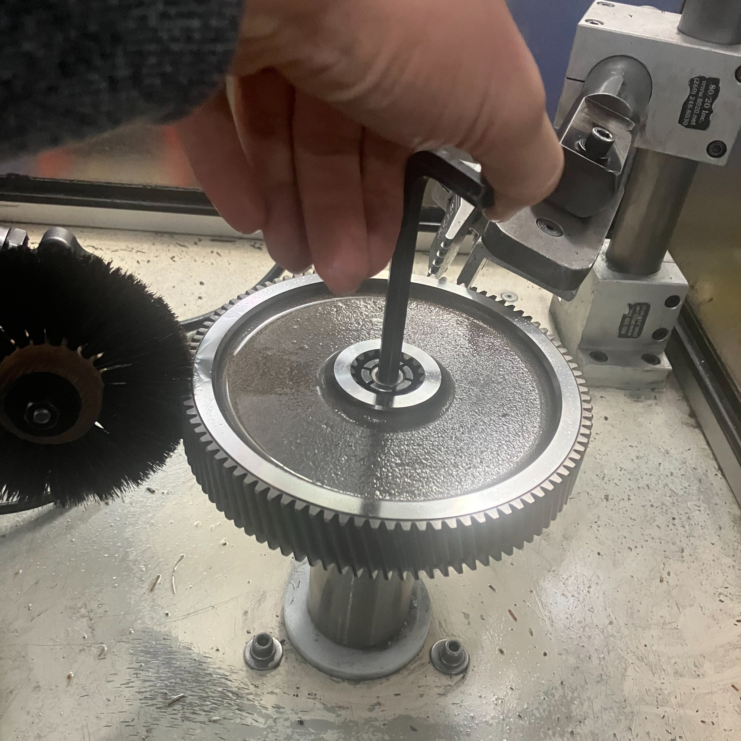
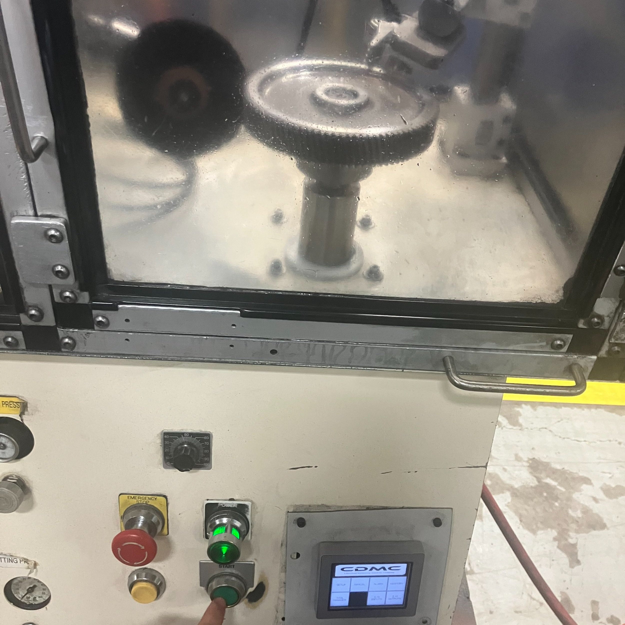
This was an old deburring machine I repurposed to clean a variety of gears.
In the photo you can see a horsehair wheel brush + angled air jet matched to the helical angle, controlled with PLC I implemented.
For the brush arm to insert to the right spot for any gear diameter/height I had to implement a sensitive pressure sensor - the air jet simply ran on a timed cycle.
Result: Automating cleaning reduced cycle time from 5 min to 30 sec per part, with reduced nicking/handling damage. (These parts were particularly sensitive to damage because they had to be cleaned before they are case hardened.)
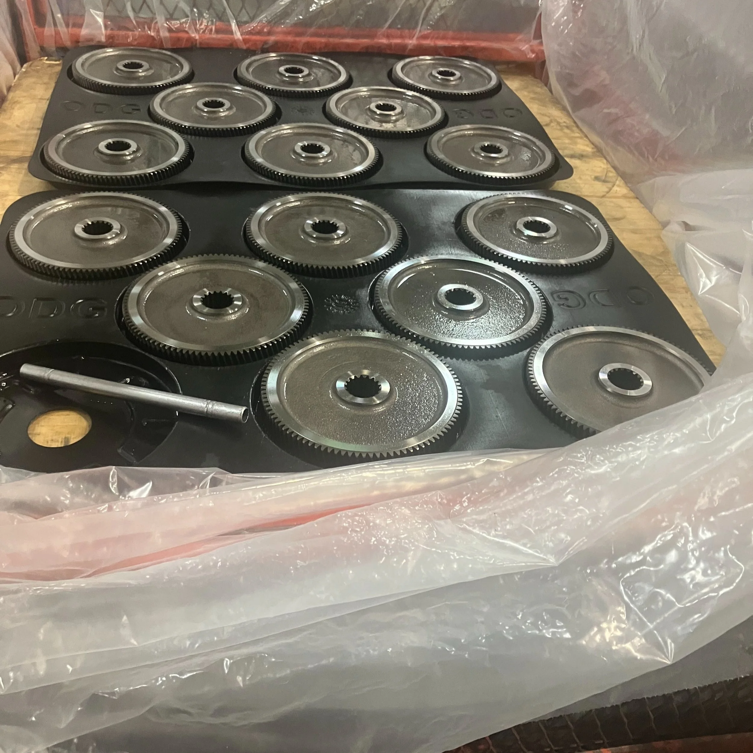
Before I administered these trays the gears were separated by loose dunnage!
By designing, proposing and implementing these separators I Improved part protection, staging, and transport
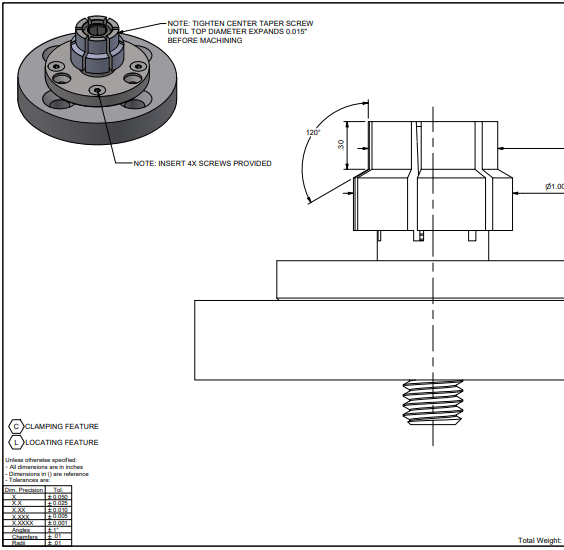
This is the front page to an assembly/drawing package I created for the tooling machinist. I implemented multiple locating features so multiple gear types can be cleaned on the same system.
This was designed with repeatable loading, stability during brushing/air-jet cleaning, and fast changeover in mind.
Sept-Dec 2023: Gear & Powertrain Manufacturing @ ON.DRIVE & GEAR
I worked for Ontario Drive & Gear, a manufacturer known for designing, manufacturing, and assembling gears/gearbox and transmission assemblies. I learned to worked in a production-minded environment where documentation and repeatability matter.

-
This is the front page to an assembly/drawing package I created for the tooling machinist. I implemented multiple locating features so multiple gear types can be cleaned on the same system.
This was designed with repeatable loading, stability during brushing/air-jet cleaning, and fast changeover in mind.
-
Before I administered these trays the gears were separated by loose dunnage!
By designing, proposing and implementing these separators I Improved part protection, staging, and transport
-
In the photo you can see a horsehair wheel brush + angled air jet matched to the helical angle, controlled with PLC I implemented.
For the brush arm to insert to the right spot for any gear diameter/height I had to implement a sensitive pressure sensor - the air jet simply ran on a timed cycle.
Result: Automating cleaning reduced cycle time from 5 min to 30 sec per part, with reduced nicking/handling damage. (These parts were particularly sensitive to damage because they had to be cleaned before they are case hardened.)
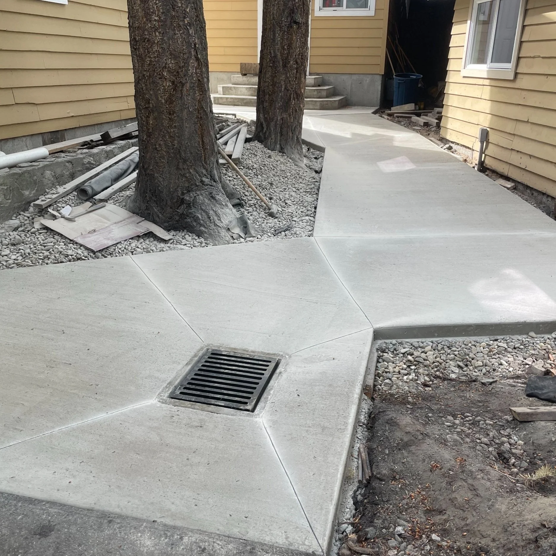
All that new concrete? Me and one other labourer used 2 wheelbarrows to wheel ~26 cubic meters in from up the hill by me while the other guys paved. For me that’s 260 wheel barrow loads at 120kg each. Over 2 days I wheeled 31200kg of concrete. That was very very very difficult.
The right image was a bit more technical - laying out those 4x4s to be just right with the slope of the hill with a bunch of snapstring was very satisfying! Wheeling the gravel down? Not so much
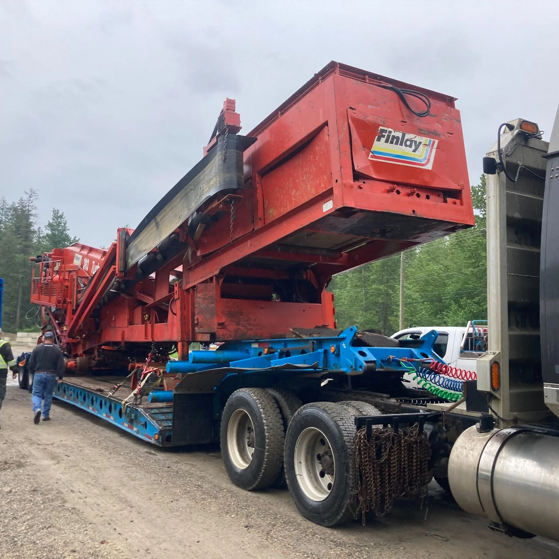
This is a smaller size gravel mine sifting machine, sorting big rocks from little rocks. It broke down often - I was welded broken mounts, replaced belts, and repaired bent sieve trays.
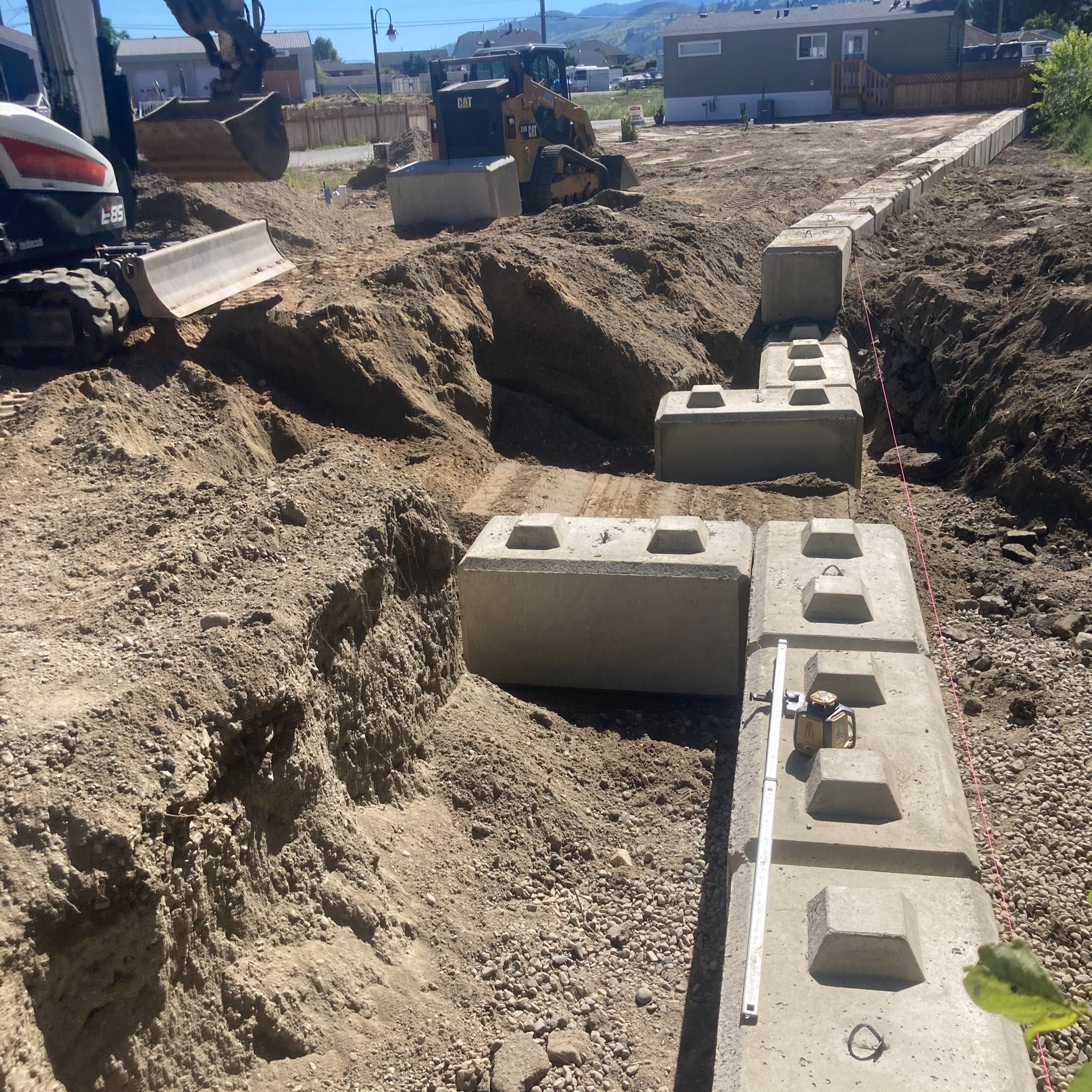
This was the first job I had the opportunity to operate an excavator on site. After practicing after work for few months I was ready to show off my new skill. All those blocks you see? I lowered them into place!
May-Aug 2022: Construction Labour @ SPOONER INDUSTRIAL
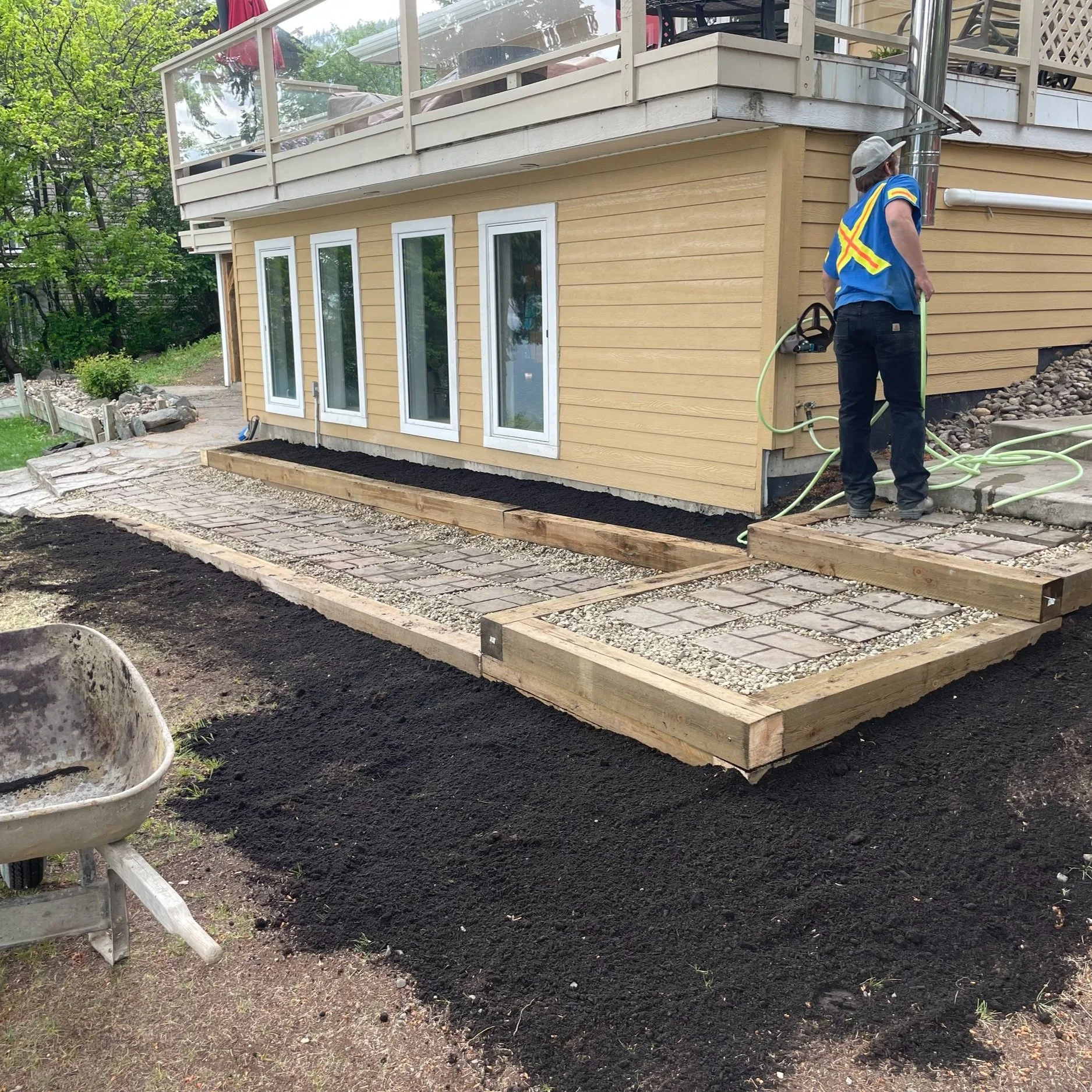
Out of any job I’ve had - I had the most autonomy and responsibility at Spooner Industrial. I laid concrete, I built decks, I installed wells, I rigged power poles, I operated gravel mining crushers/screeners, I dug septic fields, I assembled retaining walls with heavy excavators, I repaired active high volume watermains, all of which entailed back breaking labour.
I was fortunate enough to see the immediate effect of most all the work I did. The reserve down the lake where I delivered & installed a huge new water filtration system at? I was thanked at the bar the next day. That filtration system supplies 106 homes, the fire hall, the gym, and the band’s administration offices.
The septic field that flooded that I spent a week digging & filling out? Sandy Point Campground, the trailer park it was connected to didn’t have to evacuate.
The hardest day of work I ever had - when my coworker got hurt and my boss had to drive him to the hospital - leaving me alone to pour 6 cubic meters of concrete before it set under the hot sun? It was a wheelchair ramp/front pad to the Creekside Seniors Center in Chase, BC.
This job gave me an immense amount of pride in my work, pride that carries today.

-
All that new concrete? Me and one other labourer used 2 wheelbarrows to wheel ~26 cubic meters in from up the hill by me while the other guys paved. For me that’s 260 wheel barrow loads at 120kg each. Over 2 days I wheeled 31200kg of concrete. That was very very very difficult.
The right image was a bit more technical - laying out those 4x4s to be just right with the slope of the hill with a bunch of snapstring was very satisfying! Wheeling the gravel down? Not so much
-
This is a smaller size gravel mine sifting machine, sorting big rocks from little rocks. It broke down often - I welded broken mounts, replaced belts, and repaired bent sieve trays.
-
This was the first job I had the opportunity to operate an excavator on site. After practicing after work for few months I was ready to show off my new skill. All those blocks you see? I lowered them into place!
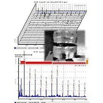
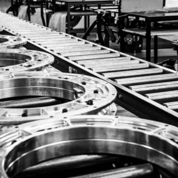
The vibration data I collected in the field (right image) was analyzed with trends/spectra in SKF Observer (it roughly looks like the left image) spikes at certain frequencies indicate certain types of failures.
These pumps aren’t moving clean water—they’re moving abrasive copper ore slurry, so wear is expected and failures must be predicted
As well as the conveyor belts - I did condition checks to estimate remaining life so pumps could be replaced during scheduled downtime—not during production.
Jan-April 2023: Vibration Analysis & NDT @ BTA RELIABILITY
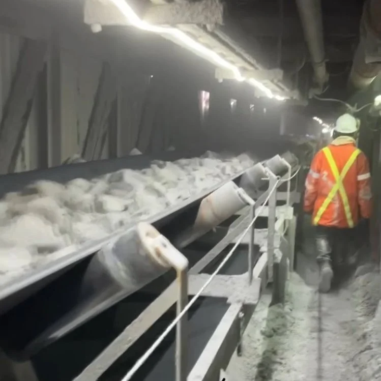
This is a conveyor belt at the largest copper mine in Canada: Highland Valley Copper. I remember there being ~50 drive/lag/tension bearings for just the conveyors I would inspect and provide maintenance reports for.
I was also contracted to write a safety audit concerned with how contractors like BTA collect data from running machinery - designing guardrails and such. HVC paid BTA $50000 for this audit.
At BTA Reliability Centered Maintenance, I did predictive maintenance work (NDT, oil analysis, vibration analysis) at heavy industrial sites like Highland Valley Copper—where unplanned downtime is brutally expensive, so the goal is to find failure early and schedule work during planned downtime.
-
This is a conveyor belt at the largest copper mine in Canada: Highland Valley Copper. I remember there being ~50 drive/lag/tension bearings for just the conveyors I would inspect and provide maintenance reports for.
I was also contracted to write a safety audit concerned with how contractors like BTA collect data from running machinery - designing guardrails and such. HVC paid BTA $50000 for this audit.
-
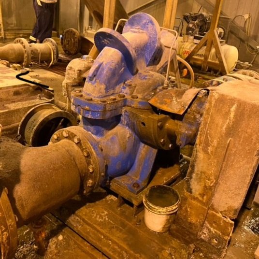
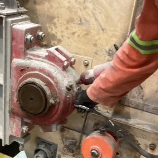
These pumps aren’t moving clean water—they’re moving abrasive copper ore slurry, so wear is expected and failures must be predicted
As well as the conveyor belts - I did condition checks to estimate remaining life so pumps could be replaced during scheduled downtime—not during production. -
The vibration data I collected in the field (right image) was analyzed with trends/spectra in SKF Observer (it roughly looks like the left image) spikes at certain frequencies indicate certain types of failures.
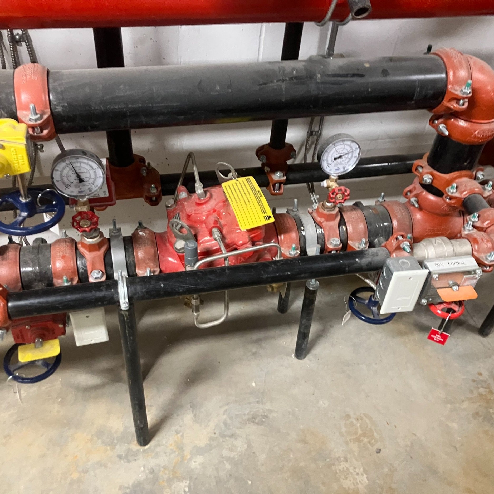
This is a manifold from a sprinkler failure investigation. To diagnose the burst head,
I documented the entire system + its conditions to support corrective action + code follow-up.
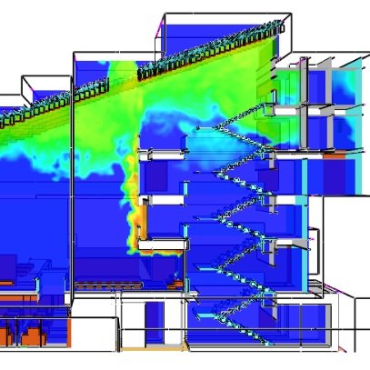
This is a smoke movement simulation built in FDS
I modeled smoke paths and accumulation - used outputs to recommend fire safety measures (e.g., compartmentation/venting strategies) aligned with BCFC / NFCC requirements.
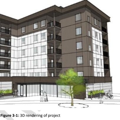
This is a figure from a code compliance report (BCFC / NFCC)
I wrote client-facing compliance reports that turn code into clear, defensible design decisions.
These reports taught me how to write rigorous documentation: structured reasoning + diagrams/figures + code.
Jan-April 2025: Fire Engineering @ SENEZCO
I worked for SenezCo, a fire science & engineering firm focused on performance-based design, code consulting, and forensic analysis. I contributed to site investigations, FDS smoke modelling, and BCFC/NFCC compliance reporting to support safe, reviewable design decisions.

-
This is a manifold from a sprinkler failure investigation. To diagnose the burst head,
I documented the entire system + its conditions to support corrective action + code follow-up. -
This is a smoke movement simulation built in FDS
I modeled smoke paths and accumulation - used outputs to recommend fire safety measures (e.g., compartmentation/venting strategies) aligned with BCFC / NFCC requirements.
-
This is a figure from a code compliance report (BCFC / NFCC)
I wrote client-facing compliance reports that turn code into clear, defensible design decisions.
These reports taught me how to write rigorous documentation: structured reasoning + diagrams/figures + code.
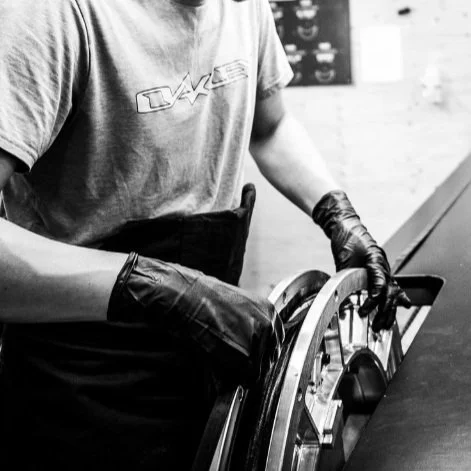
At WAO we even machined our own linkages, bolts, and insets! I was only a labourer, but every second I could sneak away I was picking at the engineers brains things like the dynamic load testing rig - which was basically a machine made to torture the bike until failure
Usually what I was doing was exactly in this photo: laying fiber into mold. I had so much fun learning how to put together such an amazing product - each wheel costs $695! I made ~7 each shift, so I made upwards of 500 wheels total - all of which I got to sign!
May-Aug 2021: Bicycle Manufacturing @ WAO COMPOSITES
The coolest high school summer job ever. My hometown - Kamloops, BC is the North American hub for competitive downhill mountain biking, home to the Juniper downhill ranch, just down the road from the host of the Canadian Downhill National Championship Sun Peaks, and home to the company that manufactures the highest quality handmade Carbon Fiber Bicycles in the world.
Laying composites into a mold is precision labour, for a full bicycle its 1000s of layers of precision cut pre-impregnated fiber!
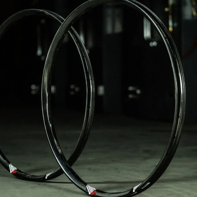
On the left are wheels about to go into the furnace for curing - I was responsible for adjusting temperature/pressure throughout the cure as the process has a very particular schedule. Quite often valves would fail, pumps would fail, and I had to improvise on the fly to make sure I saved the batch of wheels.

-
At WAO we even machined our own linkages, bolts, and insets! I was only a labourer, but every second I could sneak away I was picking at the engineers brains things like the dynamic load testing rig - which was basically a machine made to torture the bike until failure
-
Usually what I was doing was exactly in this photo: laying fiber into mold. I had so much fun learning how to put together such an amazing product - each wheel costs $695! I made ~7 each shift, so I made upwards of 500 wheels total - all of which I got to sign!
-
On the left are wheels about to go into the furnace for curing - I was responsible for adjusting temperature/pressure throughout the cure as the process has a very particular schedule. Quite often valves would fail, pumps would fail, and I had to improvise on the fly to make sure I saved the batch of wheels.